- 您现在的位置:买卖IC网 > Sheet目录312 > AT25256B-SSHL-B (Atmel)IC EEPROM 256KBIT 20MHZ 8SOIC
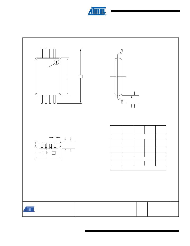
8A2 – TSSOP
3
2 1
Pin 1 indicator
this corner
E1
E
L1
N
L
Top View
End View
COMMON DIMENSIONS
(Unit of Measure = mm)
b
A
SYMBOL
D
E
E1
A
MIN
2.90
4.30
–
NOM
3.00
6.40 BSC
4.40
–
MAX
3.10
4.50
1.20
NOTE
2, 5
3, 5
e
A2
A2
b
0.80
0.19
1.00
–
1.05
0.30
4
D
e
0.65 BSC
Side View
L
L1
0.45
0.60
1.00 REF
0.75
Notes:
1. This drawing is for general information only. Refer to JEDEC Drawing MO-153, Variation AA, for proper dimensions,
tolerances, datums, etc.
2. Dimension D does not include mold Flash, protrusions or gate burrs. Mold Flash, protrusions and gate burrs shall
not exceed 0.15mm (0.006in) per side.
3. Dimension E1 does not include inter-lead Flash or protrusions. Inter-lead Flash and protrusions shall not exceed
0.25mm (0.010in) per side.
4. Dimension b does not include Dambar protrusion. Allowable Dambar protrusion shall be 0.08mm total in excess
of the b dimension at maximum material condition. Dambar cannot be located on the lower radius of the foot.
Minimum space between protrusion and adjacent lead is 0.07mm.
5. Dimension D and E1 to be determined at Datum Plane H.
5/19/10
20
TITLE
Package Drawing Contact: 8A2, 8-lead 4.4mm Body, Plastic Thin
packagedrawings@atmel.com Shrink Small Outline Package (TSSOP)
Atmel AT25128B/256B
GPC
TNR
DRAWING NO.
8A2
REV.
E
8698C–SEEPR–8/11
发布紧急采购,3分钟左右您将得到回复。
相关PDF资料
AT25256T2-10TI-2.7
IC EEPROM 256KBIT 3MHZ 20TSSOP
AT25320AY6-10YH-1.8
IC EEPROM 32KBIT 20MHZ 8DFN
AT25640T1-10TI-2.7
IC EEPROM 64KBIT 3MHZ 14TSSOP
AT25DF321-SU
IC FLASH 32MBIT 70MHZ 8SOIC
AT25F1024AN-10SU-2.7
IC FLASH 1MBIT 33MHZ 8SOIC
AT25F2048N-10SU-2.7
IC FLASH 2MBIT 33MHZ 8SOIC
AT25F4096W-10SU-2.7
IC FLASH 4MBIT 33MHZ 8SOIC
AT25HP512W2-10SI-2.7 SL383
IC EEPROM 512KBIT 10MHZ 16SOIC
相关代理商/技术参数
AT25256B-SSHL-B-RET
制造商:Atmel Corporation 功能描述:
AT25256B-SSHL-T
功能描述:电可擦除可编程只读存储器 256Kbit; SPI Bus High Spd; Mode 0 & 3 RoHS:否 制造商:Atmel 存储容量:2 Kbit 组织:256 B x 8 数据保留:100 yr 最大时钟频率:1000 KHz 最大工作电流:6 uA 工作电源电压:1.7 V to 5.5 V 最大工作温度:+ 85 C 安装风格:SMD/SMT 封装 / 箱体:SOIC-8
AT25256B-SSHL-T SL901
制造商:Atmel Corporation 功能描述:IC EEPROM 256KBIT 20MHZ 8SOIC
AT25256B-SSHL-T
制造商:Atmel Corporation 功能描述:Serial EEPROM IC
AT25256B-XHL-B
功能描述:电可擦除可编程只读存储器 256Kbit; SPI Bus High Spd; Mode 0 & 3 RoHS:否 制造商:Atmel 存储容量:2 Kbit 组织:256 B x 8 数据保留:100 yr 最大时钟频率:1000 KHz 最大工作电流:6 uA 工作电源电压:1.7 V to 5.5 V 最大工作温度:+ 85 C 安装风格:SMD/SMT 封装 / 箱体:SOIC-8
AT25256B-XHL-T
功能描述:电可擦除可编程只读存储器 256Kbit; SPI Bus High Spd; Mode 0 & 3 RoHS:否 制造商:Atmel 存储容量:2 Kbit 组织:256 B x 8 数据保留:100 yr 最大时钟频率:1000 KHz 最大工作电流:6 uA 工作电源电压:1.7 V to 5.5 V 最大工作温度:+ 85 C 安装风格:SMD/SMT 封装 / 箱体:SOIC-8
AT25256B-XHL-T SL901
制造商:Atmel Corporation 功能描述:IC EEPROM 256KBIT 20MHZ 8TSSOP
AT25256C1-10CC
制造商:ATMEL 制造商全称:ATMEL Corporation 功能描述:SPI Serial EEPROMs
